Originally posted 2018-11-19 14:13:40.
Automobile Wiring & How It Works

All the components in the car’s electrical system are joined through their respective switches to the battery and generator. These supply the power that is converted by the components into light, heat and movement.
Each component must be connected to the power source by two conductors, one joined to the battery or generator positive terminal and the other to its negative terminal.
This is because an electrical current will flow in a circuit only when a path for it exists from the power source, through the component and back to the power source again.
For this reason, the action of turning on a switch is often referred to as ‘completing a circuit’, and turning it off as ‘breaking the circuit’.
Nearly all cars have a steel body shell which is used as one of the two conductors and is known as the ‘earth’ connection. This reduces by half the amount of wire required and simplifies the electrical circuits.
Cars with glass-fiber bodies and special vehicles such petrol tankers, where there is a fire risk, do not use the body-work as a conductor, but have ‘earth’ return wires which should be occasionally checked for tightness.
How Automobile Wiring Works

All substances and materials are made from atoms, each of which has a positively-charged nucleus and a number of negatively-charged particles called electrons which orbit around it in much the same way as the moon moves around the earth.
The number of electrons in an atom depends on the material of which it is part. Normally, the negative charge of the electrons balances the charge of the nucleus.
However, if an atom loses an electron, it has a positive charge, and if it gains one it will have a negative charge.
In a battery, the positive plates have many atoms which have lost electrons t the negative plates by the chemical actions of the battery.
This results in a condition of imbalance. The imbalance creates a pressure in the form of a voltage which is trying to return the excess electrons from the negative plate to the positive plate.
If an electrical circuit is connected to the battery and switched on, electrons from the atoms of the conducting wire are attracted into the battery positive plate, and at the same time electrons are pushed into the wire connected to the negative plate.
The movement of electrons through the circuit can be likened to a long, thin tube filled with balls. If an extra ball is pushed in at one end, another ball will immediately fall out of the other end.
Electrical current flowing in a circuit follows this principle, but at the speed of light.

Some substances, such as copper have atoms from which electrons can be moved without too much difficulty.
These are called conductors. Other substances, where the bond between the electrons and nucleus is very strong and from which electrons cannot be moved are known as insulators.
Polarity of car electric wiring
The polarity of a car battery will indicate which terminal will be connected to the bodywork and ‘earthed’.
Most vehicles have the negative terminal joined to the body and are termed ‘negative earth’ vehicles.
It is important to know your car’s electrical polarity, for if components such as radios, tape players and alternators.
Which are designed for negative earth cars are fitted to a car with a positive earth arrangement, which is a pattern that the positive terminal is connected to the body, such appliances will be damaged.
Heater or washer motors connected to cars of the wrong polarity may run backwards.
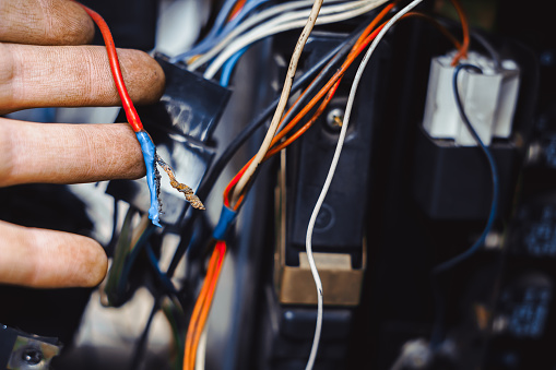
Car electric cables
The cable used in a car is purpose-built with insulation that is unaffected by petrol, oil or high under-bonnet temperatures.
Its copper conducting core is made up of a number of strands twisted together to make it flexible and to prevent it from breaking, even if it is repeatedly bent backwards and forwards.
Household wire should not be used in cars because it is not suitable for th that purpose.
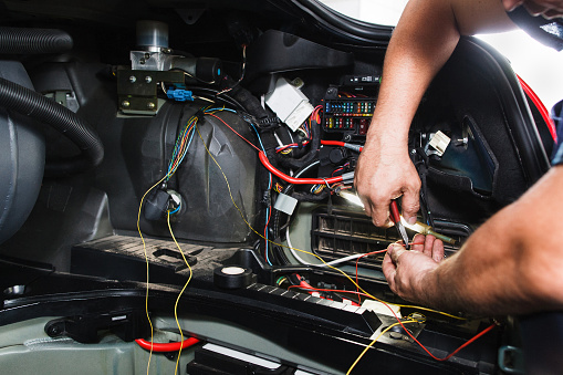
Most of the wiring in a car is made into a ‘loom’, either by bundling the cables together and wrapping them with tape, fitting them into a plastic sleeve, or by laying them side by side and welding their insulation to a backing strip.
A cable’s current-carrying capacity is determined by the number and thickness of the copper strands inside the insulation.
A 17.5amp cable, for instance, has 28 strands of wire, each 0.30mm thick and is expressed as 28/0.30. The table identifies other wire capacities.
Because cable capacities are quoted in amps and the current consumption of an accessory is usually given in watts, the watts must be converted to amps by diving them by the battery voltage.
For example, on a 12-volt system, a 60-watt fog lamp would draw 60/12+5amps, and a cable of at least 5amps capacity must be used when connecting it.
| Grade | Conductor cross session | Maximum continuous current | |
| 14/0.25
14/0.30 19/0.30 21/0.30 28/0.30 35/0.30 44/0.30 65/0.30 97/0.30 | 0.7mm2
1.0 mm2 ———– 1.5 mm2 2.0 mm2 2.5 mm2 3.0 mm2 4.5 mm2 7.0 mm2 | 6 amps
8.75 amps 11.75 amps 12.75 amps 17.5amps 21.75 amps 27.5 amps 35 amps 50 amps | Cable grades are quoted as the number and thickness of the copper conductor strands inside. A 6 amp 14/0.25 cable has 14 strands, each 0.25 mm in diameter. |
Color coding arrangement in automobile wiring
Because car manufacturers bunch their cables together in a loom, different colored insulation is used to identify wires. Unfortunately, there is no international standard color code for vehicle wiring.
But most manufacturers use one principal color for each electrical system, such as the headlights, sidelights, and ignition switch-controlled accessories.
They then use different colored stripes to identify sub-circuits in each system.
For instance, on a headlight circuit using blue-colored cables, blue cables with a red stripe may feed current to the dipped beams, while blue cables with a white stripe feed the main beams.
Although color-coding helps identification, fault-finding requires some sort of map of the wiring system. Known as the wiring diagram.
Only automobile manufacturers include the diagram in their handbook, and it is usually necessary to obtain a workshop manual to study it in full.