TD 70 E Engine Valve Grinding and Decarbonizing Procedures
Tool: Torque Wrench:Q-350 Nm (0-25 kgf m = 0-260 Ibf ft)
Procedure for the removal of cylinder Head
- Empty the Cooling system
- Remove the compressor attached to the TD 70 E Engine. Remove the delivery pipes, leak-off fuel lines, and injectors. Place on blanking-off caps.
- Remove the exhaust and coolant connection pipes between the two cylinder heads.
- Remove the induction and exhaust manifolds and the rocker casings.
- Remove the rocker arm mechanism and pushrods.
- Remove all the bolts which hold the cylinder heads and lift them off the cylinder heads.
- Remove the cylinder head gaskets, rubber seals, and guides from the cylinder block.


Procedure for the Valve Grinding and its seats
Remove the valves and place them in a stand.
Grind the valves in a machine. The grinding wheel should be of ceramically bonded aluminum oxide with a granular size of 70 and a hardness rating of M-N with a structure of 8.
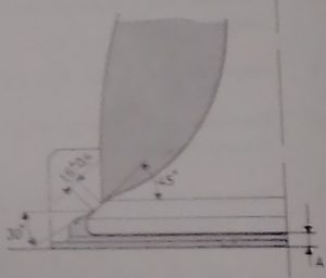
Adjust the grinding machine to an angle of 44.5 degrees for the exhaust valve and 22.5 degrees for the inlet valve.
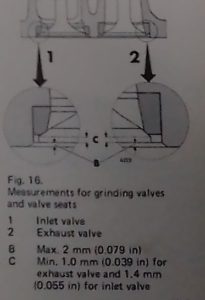
If the edge C ( from the Diagram of the Valve provided on the post) of the valve disc is less than 1.4mm (0.055 in) on the inlet valve and 1.0 mm (0.039 in) on the exhaust valve, or if the valve stem is bent, scrap the valve.
Machine the valve seat inserts. Before starting the grinding operation, the valve guides should be changed and reamed if the wear limits are exceeded. With a new valve, the clearance between the valve guide and valve stem should be max. 0.15 mm (0.006 in) for the inlet valve guide and 0.17 mm (0.007 in) for the exhaust valve guide.
Machine the valve seat inserts. Do not grind off more materials than necessary. Reduce the exhaust valve seat to the correct seat width, which is 1.6 mm (+/-) 0.4mm. The inlet valve seat angle is 30 degrees and the exhaust valve seat angle is 45 degrees. If the Distance A from the below diagram provided exceeds 2 mm when checked with a new valve, the seat insert should be changed, see under “Changing valve seat inserts”
A new seat should be ground down so far that the distance between the cylinder block face and valve disc is 0.7-1.1 mm. the grinding wheel should be of ceramically bonded aluminum oxide with a granular size of 70 & a hardness rating of M-N with a structure of B. Checking and dressing of the angle should be done in a dressing device where the wheel is dressed to the correct angle and surface finish with a diamond. The grinding wheel should have the same number of degrees as the contact surface of the valve seat insert. For inlet Valve 30 degrees, For the exhaust Valve 45 degrees.
Grind in the valves with paste. When the sealing surfaces appear to be good, check them with marking paint.
Check the valve springs for straightness, length, and tension. This is done in a spring-tester. Change the springs if they do not maintain the values given in the specifications.
Conclusion
With everything in order, proceed to assemble the valves back and conduct your leakage test on the valves.
