Components of CAD System
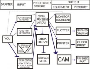
For large, medium, and small system applications, CAD systems can comprise various combinations of devices. The user’s needs will determine the specific package to be selected.
Various types of drawings such as check prints or finished drawings referred to as hardcopy may be preferred by certain companies.
While some companies that are fully automated may not require any drawing whatsoever, but rather link the drawing with Computer-Aided Manufacturing (CAM) for automated manufacturing.
A typical CAD system consists of two main parts: Hardware and software. Each system element can generally be categorized as one of the following types: input and output; processing and storage.
HARDWARE COMPONENTS OF CAD
The hardware components consist of the computer and the input-output (I/O) devices. Input devices are generally used to transfer information from a human or storage medium to a computer.
A keyboard is the standard input device used to transmit alphanumeric data to the system.
The input devices can function keyboard, graphics tablet, light pen, joystick, mouse, etc.
While the output devices can be a hard copy unit, printers, plotters, videotape, Computer Output Microfilm (COM), Computer-Aided Manufacturing (CAM), etc. in many cases, the design may never be produced on paper.
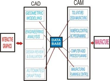
The data generated by a CAD system can be directly utilized by a CAM system; for example, it may be transmitted to CNC programming routines used to produce components.
Hardware Requirement for CAD
The following are the hardware requirement for CAD;
The hardware requirements for CAD rank among the most equipped for the CAD/CAM operations. CAD programs will utilize as many resources as you can afford to put at their disposal.
Some of the minimum specifications/options to look for when considering a PC for serious Computer-Aided Design/Drafting (CADD) work are:
- RISC-based processor; Pentium-based processor, 486D x processor, 486D x 2processor, with a numeric processor in that order of preference.
- 16k internal cache and 256k external cache
- 8MB RAM minimum, 32MB RAM recommended
- Hardware-based disk accelerator floppy disk, CD-ROM
- Hardware-based graphics accelerator with at least 1MB VRAM. Currently, the fastest graphics accelerator in the market is the ‘IMAGINE 928’ PC card
- PCI or VERSA local bus
- Plug and play architecture
- Non-interlaced super VGA monitor preferably microprocessor controlled
- 5 floppy disk drive
- Optional multi-media and other accessories
- Monitor
- Printers and plotters
- Keyboard
- Digitizer, puck, and mouse.
SOFTWARE COMPONENTS OF CAD
CAD program consists of hundreds of functions in the software aspect that enable the user to accomplish any drawing tasks.
Tasks involving drawing, editing, and displaying a given drawing, printing or saving it, and other similar operations require software components of the CAD.
Some CAD systems now have the Window platform, aimed at making the extensive use of point-click-drag- and cut-copy-paste functions to reduce the modeling time.
The software functions are organized into modules that provide easy access to all the commands.
The module divisions are as follows; draw, edit, data input, function control, storage, and management.
Special CAD programs may consist of specialized functions such as layers, databases, and 3D.
By classifications, CAD system software can be listed as follows:
- Operational software
- Graphics software
- Application software
- User software
Operational Flowchart of a CAD System
Below is an operational flowchart of a CAD system;

